
Products
Products

 Installation & Application(安装应用)
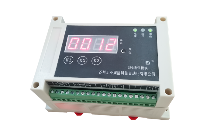
 NKP-LJ-04 SPD Communication Module
The NKP-LJ-04 SPD communication module can be used in conjunction with power surge protectors during installation. It utilizes a DIN35 rail mounting method and can be installed in power distribution boxes and various standard cabinets.
Wiring Instructions:
Connect the working power terminals to the protected side of AC or DC power surge protectors.
Connect the sampling current transformer in series with the down-conductor of the surge protector.
Connect the remote signaling terminals to the remote signaling contacts of the surge protector.
Connect the RS-485 serial communication terminals to the 485 bus of the remote intelligent management unit or integrated automation system (backend host computer).
Operation:
The digital display of the NKP-LJ-04 SPD communication module shows the number of lightning strikes. Buttons below the display allow configuration of communication address and baud rate, as well as operations such as resetting the counter.
Product Dimension Drawing

Port Definition
| Model | NKB-20S | Withstand Voltage | 2KV |
| Accuracy | ±0.2%, ±0.5% Optional | Shell Material | Flame-Retardant ABS |
| Rated Current Input | 0~1A, 0~5A, etc. Optional | Dimensions (W×H×D) | 55×75×120/110×75×120 (mm) |
| Output Range | 0~20mA, 4~20mA, 0~5V, 0~10V, 1~5V, etc. Optional | Weight | 0.4kg |
| Auxiliary Working Power Supply | AC220V±15%, 4VA, etc. | Mounting Method | 35mm DIN Rail Mountable |
| Working Frequency | 50±5Hz | Working Temperature | -5℃ ~ +45℃ |
| Output Ripple | <1% (Peak-to-Peak) | Storage Temperature | -20℃ ~ +75℃ |
| Input Power Consumption | Current<0.5VA, Voltage <0.5VA; * Add 1VA if Self-Powered | Relative Humidity | <80% |
| Temperature Influence | Within Standard Temperature Range, for Every ±20℃ Change, Allowable Error Variation is ±0.2%, ±0.5% | Protection Class | IP20 |
 Technical Parameters(技术参数)
 Working Power Supply: AC 220V, 2W;
Working Temperature: -5℃~ +40℃ (Storage Temperature: -40℃ ~ +70℃);
Sampling Method: With dedicated matching current transformer;
Lightning Impulse Current: 10kA to 100kA (8/20μs);
Leakage Current: AC 0.1mA to 50mA;
Operating Voltage: AC 85V to 265V;
Temperature Range: 0℃ to 50℃;
Display Mode: 4-digit 0.56-inch red high-brightness LED nixie tubes;
Local Address: Decimal 1 - 255; Defaults to 01 at power-on, settable via buttons, can be set to the same number as the connected surge arrester;
Baud Rate: 9600, 4800, 2400 bit/s optional, defaults to 9600 bit/s at power-on, settable via buttons; Equipped with RS-485 communication interface, uses standard MODBUS-RTU communication protocol to communicate with upper computer and management computer;
Maximum Count: 100 times, after reaching the maximum, counting resumes from 01;
Data Preservation: Data preserved when power off, can preserve data for up to 10 years in case of power failure;
Installation Method: DIN35 rail mounting;
Overall Dimensions: 145mm×90mm×72mm.
 Operation Method(操作方法)
 **Power-on and Initialization**
When power is first applied, the device displays "00". It retains configuration settings (lightning strike count, address, baud rate) in non-volatile memory. Upon subsequent power cycles, it resumes displaying the last recorded count and settings.
**Remote Signal Contacts**
During operation, the device monitors remote contact status changes. Open/closed states correspond to SPD failure modes as defined by the surge arrester specifications.
**Lightning Strike Counting**
Each detected lightning-induced pulse increments the displayed count by 1.
**Data Reset**
The accumulated strike count can be reset via an upper computer command. Upon reset, the display returns to "00" and the device sends a confirmation message.
**Button Operations**
Three front-panel buttons enable configuration and status checks: 1. **K1 (Menu Toggle)**: Cycles through main menus: - Press once: Enter baud rate setting mode (displays "Ba24"). - Press twice: Enter address setting mode (displays "Ad01"). - Press thrice: Return to strike count display. 2. **K2 (Value Adjust)**: - **Baud Rate**: Cycles between 2400/4800/9600 bps. - **Address**: Increments address value (1-255). 3. **K3 (Confirm/Save)**: - Exit menu and save settings. A single beep confirms changes. **Operation Notes**: - All menu settings must be confirmed with K3 to ensure proper device operation. - Default settings: Address 01, Baud rate 9600 bps. This translation maintains technical precision while adhering to international electrical standards (IEC 62305, IEEE 1587).
Ordering and Model Selection(订货选型) *Please send the inquiry email containing specific product requirements (such as model, quantity, technical parameters, etc.) to the designated email address salina@kejia.com.
(请将包含具体产品需求(如型号、数量、技术参数等)的询价邮件发送至指定邮箱 salina@kejia.com)
 Download
| File name | Product type | Download |
|---|---|---|
| NKP-LJ-05 SPD通讯模块PDF文档 | 说明手册 | Download |
