
Products
Products

 Installation & Application(安装应用)
 Achieves selective interruption of power-frequency current and lightning current, effectively protecting SPD from burnout short-circuit caused by abnormal transient overvoltage to prevent serious fire accidents.
Achieves selective interruption of power-frequency current and lightning current, effectively protecting SPD from degradation-induced starting voltage drop below supply voltage and increased power-frequency leakage current, thus preventing serious fire accidents.
When lightning current passes through SPD, the external disconnector will not trip mistakenly, ensuring the lightning protection of electrical equipment remains effective at all times.
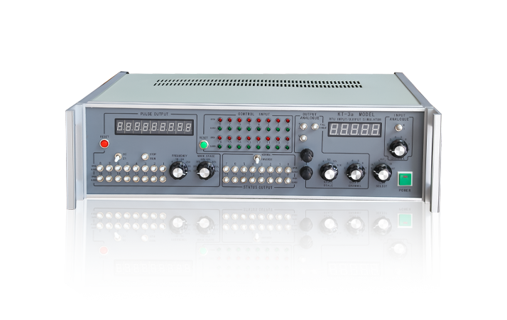
Panel Schematic Diagram
")

| Function Corresponding to Panel Serial Number | |
|---|---|
| 1. Reset Button for Pulse Count Recorder | 2. OC Gate for Pulse Counting |
| 3. Start/Stop Switch for Pulse Counting | 4. Display Table for Pulse Counting |
| 5. Reset Button for Remote Control Input | 6. Indicator Light Group for Remote Control Input Status |
| 7. Selection Switch for Polarity of Analog V/I Output | 8. Selection Switch for Analog V/I Output |
| 9. Selection Switch for Analog Full Circuit/Half Circuit | 10. Display Table for Quantity of Analog Input and Output |
| 11. Selection Switch for Analog V/I Input | 12. Selection Switch for Remote Pulse Output |
| 13. Selection Switch for Remote Pulse Frequency | 14. Selection Switch for Remote Pulse Duty Cycle |
| 15. Switch Group for Communication Status Quantity Output | 16. Main Switch for Communication Status |
| 17. Coarse Adjustment Potentiometer for Analog Output | 18. Fine Adjustment Potentiometer for Analog Output |
| 19. Amplitude Switch for Analog Output | 20. Selection Switch for Analog Output Channel |
| 21. Selection Switch for LV Test | 22. Main Switch for Working Power Supply |
| 23. Selection Switch for Analog Input Channel | 24. RTU Input for PLD Analog Quantity |
| 25. RTU Output for PLC Analog Quantity | 26. PLE3 Remote Control Input 3 |
| 27. PLE2 Remote Control Input 2 | 28. PLE1 Remote Control Input 1 |
| 29. PLA Remote Pulse Output | 30. PLB Communication Status Quantity Output |
| 31. OUT POWER Spare Output Power Supply for Remote Control Tester | 32. 33V Test Power Supply Output |
| 34. Fuse Holder for Test Power Supply | 35. Selection Switch for Test Power Supply Output and Input |
| 36. Terminal for 37V External Input Power Supply | 38. Fuse Holder for Internal 24V Power Supply |
| 39. Fuse Holder for Internal 5V Power Supply | 40. 220V AC Socket for Working Power Supply |
| 41. Fuse Holder for Working Power Supply | |
 Technical Parameters(技术参数)
 | Remote Control Status Quantity Output | Provides 16 channels of open/close signals, which are normally open contacts of the knife switch. Single-circuit or full-circuit output can be selected. When the channel switch is toggled to (OPEN), it trips; when toggled to (CLOSED), it closes. |
| Pulse Quantity (Remote Pulse) (PULSE OUTPUT) Output | Provides 16 channels of pulse signals, which are OC gate or relay contacts. Single-circuit or full-circuit output can be selected. When the channel switch is toggled to (OPEN), there is output; when toggled to (CLOSED), there is no output. Pulse frequency: 1 - 2000Hz. Pulse duty cycle: 10 - 90%. Pulse counting: 9-digit decimal accumulation. |
| Remote Control Quantity Input (CONTROL INPUT) | Provides 16 channels of trip/close signal indications. For externally connected active nodes, when separated (OPEN), the green light is on; when closed (CLOSED), the red light is on. Provides 1 channel of reset signal. |
| Analogue Quantity Output (OUTPUT ANALOGUE) | Provides 8 channels of voltage/current analogue outputs. Channels and ranges are selectable. Voltage quantity range: 0 - 10V (4 1/2-digit digital display). Current quantity range: 0 - 20mA (4 1/2-digit digital display). |
| Analogue Quantity Input (INPUT ANALOGUE) | External connection of 8 channels of voltage/current analogue inputs, with selectable display. Voltage quantity range: 0 - 10V (4 1/2-digit digital display). Current quantity range: 0 - 20mA (4 1/2-digit digital display). |
| Standby Power Supply | Provides a DC 24V, rated current 0.5A DC power output for signal debugging. |
| Operating Conditions | Temperature: 0 - 40°C. Humidity: < 85% |
| Operating Power Supply | AC 220V ± 10%. Power consumption < 40W |
| External Dimensions | 120×440×310 (mm) |
| Weight | < 5.5kg |
 SCB Trip Remote Signal Accessory(SCB脱扣遥信附件)
 ")
Ordering and Model Selection(订货选型) *Please send the inquiry email containing specific product requirements (such as model, quantity, technical parameters, etc.) to the designated email address salina@kejia.com.
(请将包含具体产品需求(如型号、数量、技术参数等)的询价邮件发送至指定邮箱 salina@kejia.com)
 Download
| File name | Product type | Download |
|---|---|---|
| KT-3a型便携式RTU输入/输出模拟器PDF文档 | 说明手册 | Download |
